Alex Kaplan joins RIT

Remote Inspection Technologies is pleased to announce the addition of Alex Kaplan to our sales team as National Technical Sales Representative.  Alex has been working with RIT as a contractor since the inception of the company, and will now take on a full time position.  He will be working out of New York City – enhancing RIT’s presence in northeast markets.

Alex has been in the robotics field for over a dozen years, with a range of experience including assembly and manufacture, research and development, and over 6 years of field operations and project management.  His technical knowledge, along with his experience working with customers in the field, make Alex a valuable asset to RIT and our customers.  We are excited to have Alex on the team!

Alex Kaplan can be reached on his direct line at 985-662-1446.  You can also call our National Sales Manager, Pete Weber, at 619-847-1097, or our main office at 985-662-0755.

For more information about Remote Inspection Technologies and the range of inspection and survey services we offer our customers, please visit our website at http://RiTech.com
Utility Location Theory of Operation

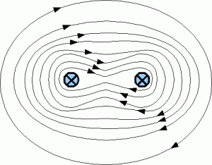
Utility Locators work in a number of different modes. The mode that offers the highest  level of accuracy at longer ranges is when the line (conductor) that is to be detected can be “Illuminated” using a Tone Generator that sends a low voltage AC signal down the pipe or line. This mode is commonly called the “Direct Connection” mode and requires that the Tone Generator be physically connected to the conductor, such as a pipeline valve, and needs to be grounded, at some distance, perpendicular to the conductor.  The frequency of the signal can be set on the Tone Generator and is selected based on the environmental conditions present at the site. Generally with a lower frequency you get a longer range (distance down the pipe and burial depth) and a slightly lower accuracy. Higher frequencies are typically used for shallow burials or areas that are electromagnetically noisy.  In applications where burial depths are greater than 2′ and/or there are long distances between the connection point for the Tone Generator and the area where the utility locating is to be attempted, a higher frequency (512Hz) should be chosen.  The AC current associated with the Tone Generator’s signal creates an alternating magnetic field around the line that can be detected by the Locator unit’s antennas. The antenna array in the locator is able to very accurately determine the direction the pipeline is running, the locator’s position perpendicular to the direction the line is running and the pipeline’s depth. Utility Locators measure depth to the center of the detected magnetic field and In most cases the center of the magnetic field is at the center of the pipe. In cases where the pipeline splits into two lines that run parallel to one another, the magnetic field becomes more complicated. Because the 2 lines are electrically coupled the Tone Generator’s signal cannot be isolated to one side or the other. This results in a combined magnetic field similar to the one in the figure below. Because the Locator is trying to detect the center of the magnetic field, the locator unit effectively locates the midpoint between the 2 lines. If the lines are shallow or the space between them is far enough apart, there is a potential to identify the two lines individually. Further testing will need to be done to determine under what circumstances resolution of 2 parallel electrically coupled lines would be possible.

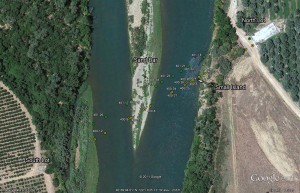
When utility locator technology is used in conjunction with survey grade geo-positioning and hydrographic survey equipment a very precise utility location and depth of burial survey can be accomplished, even when the buried utility is crossing under bodies of water.

Pipeline Locating Map Example

Combined Magnetic Field Example

http://www.remoteinspectiontechnologies.com/


Multiple Sensor Approach to Internal Pipeline Inspection

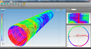
Three dimensional model of corrugated pipe created using the Red Eye LIDAR.

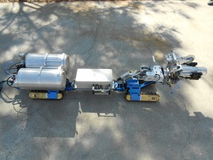
Historically internal pipe inspection has been conducted visually, using a video camera mounted on a robotic transport system (CCTV). But as sensor technology has progressed, so has the desire to collect more quantifiable data from the ID of pipeline. RIT recognized the lack of data being acquired by traditional CCTV and responded by creating a long range robotic platform with multiple sensors specifically designed for internal assessment of pipeline. The “Red Eye” platform is equipped with a 360 degree rotating LIDAR sensor that is used to create a very accurate three dimensional model of the ID of pipeline. The “Red Eye” also utilizes an ultrasonic thickness sensor that uses localized guided waves to detect pipe wall loss in metal piping systems. In addition to the LIDAR, and UT sensors, the “Red Eye” also has a pipe profiling sonar for wet applications and traditional CCTV cameras to visually document the pipeline. All of this put together insures no matter what the scope of the inspection, RIT has the right tool for the job.

The Red Eye inspection vehicle.


ASW Piping in High Definition

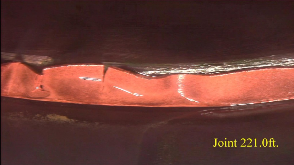
In 2011 RIT completed an inspection of an auxiliary salt water piping system for a major US utility in there nuclear power facility. The inspection was conducted using a pan/tilt/zoom camera with full 1080I resolution, integrated on to a robotic tractor specifically designed for large diameter pipe inspection. The whole world is moving towards true high definition video and RIT is one of the first service contractors in the world to provide high definition video in an industrial application.

www.ritech.us

ASW Joint